Sous-traitant de précision fiable pour les ateliers d'outillage


Comment réduire la déformation des poinçons d'estampage minces
Thin precision tooling components can be difficult to keep dimensionally stable during machining. Even when the required dimensions are achievable, a part may bend, twist or change shape during material removal or after it is released from its fixture.
This is often referred to as machining distortion ou part warping.
For precision punches, inserts and other thin tooling components, distortion can affect straightness, flatness, profile accuracy and overall dimensional consistency. Understanding the causes is the first step toward planning a more reliable manufacturing process.
1. Why Are Thin Parts More Susceptible to Distortion?
Thin components have lower structural stiffness than thicker parts. Depending on their length, thickness, geometry and material, they may be more sensitive to machining forces, clamping pressure and changes in internal stress.
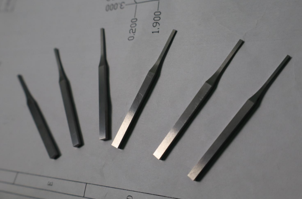
A part that appears stable during machining may move after it is unclamped. In other cases, dimensional changes may become apparent as more material is removed or as the component progresses through subsequent operations.
The risk is not determined by thickness alone. Long, narrow punches, thin inserts and components with uneven cross-sections may each present different challenges.
For this reason, dimensional stability should be considered throughout the manufacturing process, not only during the final grinding operation.
2. Residual Stress and Material Removal
Residual stress can remain in a material after earlier manufacturing operations, such as material preparation, heat treatment or rough machining.
When material is removed, the existing stress balance changes. If the stress distribution is uneven, the component may bend or twist as machining progresses.
This is one reason why simply achieving a precise cut or grinding dimension does not always guarantee that a thin part will remain straight and stable.
For components with a higher risk of distortion, the process may need to include an appropriate stress-relief step before precision finishing.
The timing and method depend on the material grade, heat-treatment condition, hardness requirements and component geometry.
3. Workholding Can Also Affect Dimensional Stability
Clamping is necessary to keep a workpiece stable during machining, but excessive or uneven clamping pressure can introduce another source of distortion.
A thin component may be forced into a flatter position while it is clamped. Once the clamping force is released, it may spring back, revealing a change in flatness or profile.
For suitable ferromagnetic materials, an electromagnetic chuck can be an alternative to mechanical clamping. It can reduce the need for concentrated mechanical clamping forces and may help minimize clamping-induced distortion.
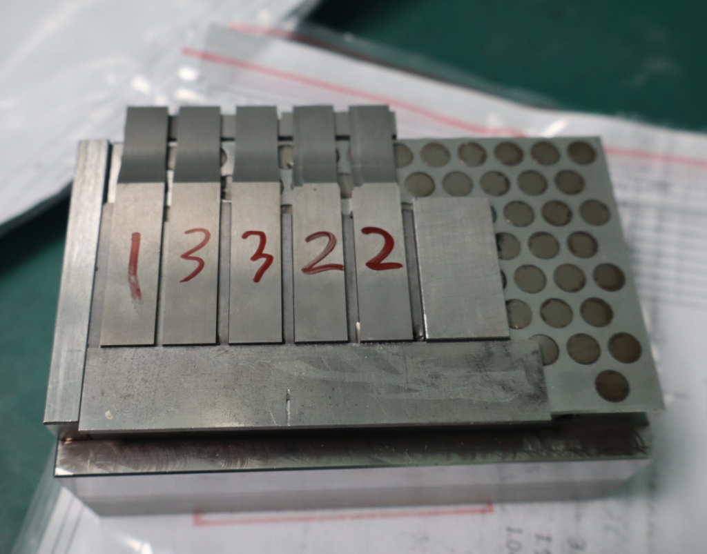
However, magnetic holding is not suitable for every material or geometry. The available contact area, magnetic holding force, workpiece thickness and grinding conditions must all be considered. Thin or flexible components may also require additional support to remain stable during machining.
The goal is not simply to hold the part firmly, but to support it without unnecessarily influencing its shape.
4. Why Does the Machining Sequence Matter?
A suitable machining sequence can help reduce the risk of distortion before the component reaches its final dimensions.
For thin precision tooling components, several process considerations may be particularly important.
Step 1: Rough machining
Remove the main material allowance while leaving sufficient stock for subsequent finishing. The amount and distribution of material removed should be considered in relation to the component’s geometry and potential stress imbalance.
Step 2: Consider stress relief after rough machining
For components susceptible to distortion, stress-relief annealing or an appropriate natural-aging process may be considered after rough machining and before precision finishing.
These methods are not interchangeable in every application. The correct choice depends on the material, its existing heat-treatment condition, hardness requirements and dimensional stability needs. Any thermal treatment must be compatible with the required material properties.
Natural aging should not be assumed to provide the same degree or speed of stress relief as a qualified thermal process.
Step 3: Plan precision grinding carefully
During precision grinding, the material removal strategy matters. Where the component geometry allows, alternating grinding between both sides can help balance material removal rather than concentrating it on one side for too long.
This approach may help reduce uneven changes during finishing, although it cannot guarantee that distortion will be eliminated. Grinding allowance, wheel conditions, cutting parameters, workpiece support and inspection points must also be considered.
Step 4: Inspect dimensional stability throughout the process
Intermediate checks can help identify movement before the component reaches its final finishing stage. Depending on the part, relevant characteristics may include thickness, straightness, flatness and critical profile dimensions.
These checks can provide useful feedback for adjusting the remaining process steps.
5. Can Profile Grinding Help with Thin Precision Components?
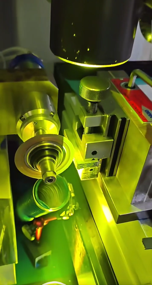
Profile Grinding (PG) is used to produce precise contours, steps, corners, radii and other critical geometries on suitable tooling components.
For thin punches and inserts, PG can be an effective finishing option when the required geometry and material are suitable for the process.
Its contribution should be considered as part of the overall manufacturing route, rather than as an isolated operation. Workpiece positioning, datum selection, grinding allowance, support and the order of material removal can all influence the final result.
Depending on the component, a manufacturing route may combine wire EDM, precision EDM, surface grinding and Profile Grinding. Each process has a different role, and the appropriate sequence depends on the drawing and the component’s dimensional requirements.
It is also important to recognize that PG cannot automatically eliminate distortion caused by residual stress, unsuitable workholding or an inappropriate machining sequence. If a component is already distorted, the available finishing allowance and the cause of the distortion must be evaluated before deciding whether further grinding is appropriate.
The objective is to plan the process so that the required geometry can be achieved while managing the risks of dimensional movement.
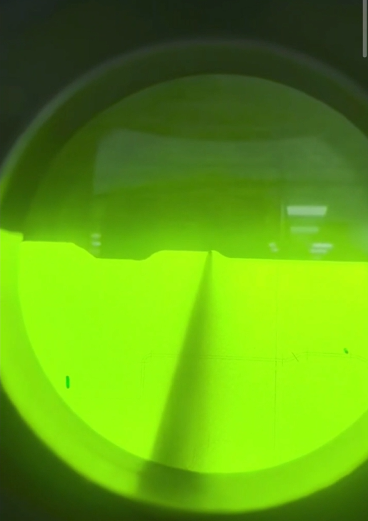
6. Why Final Inspection Matters
A thin component may behave differently while clamped and after it is released. Therefore, inspection conditions matter as much as the measurement method itself.
Depending on the drawing and application, final inspection may include:
- Critical profile dimensions
- Thickness and dimensional consistency
- Straightness or flatness, where specified
- Radii, corners and transition areas
- Other drawing-defined tolerances
For flexible components, the inspection method should avoid introducing unnecessary force that could affect the measurement. Where relevant, the inspection plan should also clarify whether the requirement applies in a free state or under a defined fixture condition.
The purpose is to verify the actual required geometry, not simply to confirm that the part matched a dimension while held in a particular position.
7. Planning a More Reliable Route for Precision Tooling Components
Thin-part distortion rarely has a single universal cause. Residual stress, material removal, workholding, component geometry and finishing strategy can interact in different ways.
For precision punches, inserts and other critical tooling components, a more considered process may include:
- Evaluating distortion risks before machining
- Considering an appropriate stress-relief step after rough machining
- Balancing material removal during precision grinding
- Reducing unnecessary clamping forces where practical
- Checking dimensional stability at suitable stages
- Selecting the finishing process according to the required geometry and tolerances
At Hepha Precision, we focus on Profile Grinding, wire EDM and precision EDM for coups de poing, inserts et other critical tooling components. We assess the drawing, material and dimensional requirements to help identify a suitable manufacturing route.
If you are dealing with thin tooling components that are difficult to keep dimensionally stable, contact Hepha Precision to discuss your drawing and manufacturing requirements.
 English
 Korean
 Japanese
 Spanish
 Portuguese
 French
 German